Anyways this post will serve as my mini dev blog for a FPV drone and 6-axis flight controller.
Why
I love a challenge. My main interest in RC flying is FPV. I don't have years of RC flying experience, so I'll need something very intuitive. And it would be awesome if it actually performed to the standards of off the shelf quadcopters, so it will need to be fast and highly maneuverable.
I'd like to make a custom remote control because the existing dual joystick design just seems like carryover from winged craft. Also the RC standard of transmitting the control signal as PPM seems like a hamstrung design the industry has maintained from pre on-board flight controller days.
How
The quadcopter hobby community is vast and open to do-it-yourselfers, so no shortage of support. The marketplace is large and caters to DIYers, components are cheap-ish and often designed to be widely compatible. So the bulk of the parts needed can be purchased off the shelf and assembled with little effort.
For the input device I plan to use a small "Stewart platform" configuration to control 3-axis and throttle in one hand. (an example of using a stewart platform input Six-Axis Joystick)
Also couple examples of using serial data instead of PPM for RC:Artiom K's Quadcopter DIY NRF24l01 and Data telemetry with MultiWii integrated nRF24L01 - has a nice breakdown of his project
Stretch goals:
Alarm for finding lost craft
Tilt rotor frame
On Screen Display (OSD)
GPS
Proximity sonar, IR, laser
EL wire or panels
FPV Video Transmitter/Receiver and Display

Got the video transmitter, receiver, and display working pretty quickly as they came together in the Quanum goggle set. Range and quality seem fine, but I don't have anything to compare to really.
Flight Controler

My entire flight controller and RC controller code is available here : GitHub
Awesome reference on how an accelerometer, gyroscope, and magnetometer(compass) work, and how to combine them together to get useable information.
Sensor Fusion on Android Devices: A Revolution in Motion Processing
Also a comprehensible and accurate description of PID.
Flite Test - P, I, and D gains-in-a-nutshell
Flite Test - P, I, and D gains-in-a-nutshell
Motor Control
First successful attempt to drive the speed controller / motor using the Teensey LC with Arduino IDE's generic analogWrite function. Even though I had read many places ESC's work between a 1-2ms pulse width I was having a bit of trouble understanding what that meant since typically PWM is talked about in terms of frequency(referring to the period length in hz) and duty(as a percentage of the period the signal is high).
This is the code/math I used to get it to work and make it easier to test different frequencies.
const int motorPin = 9;
// pwmFrequency in hz, for PWM / Analog Write Frequency, 1hz = 1000ms period
const int pwmFrequency = 50;
// pwmRes is the bit presision of the PWM / Analog Write
const int pwmRes = 16;
// 0 to pwmMax is the number range at pwmRes, 8bit = 255, 16bit = 65535
const int pwmMax = pow(2, pwmRes)-1;
// escMin is the pwm value that results in a 1ms pulse width, which is the esc's min throttle
// ex. 3276.75 @ 50hz 16bit, 31456.8 @ 480hz 16bit
const int escMin = 0.5 + (1.0/(1000.0/float(pwmFrequency))) * pwmMax;
// escMax is the pwm value that results in a 2ms pulse width, which is the esc's max throttle
// ex. 6553.5 @ 50hz 16bit, 62913.6 @ 480hz 16bit
const int escMax = 0.0 + (2.0/(1000.0/float(pwmFrequency))) * pwmMax;
In the setup
pinMode(motorPin, OUTPUT);Then in the main loop.
analogWriteFrequency(motorPin, pwmFrequency);
analogWriteResolution(pwmRes);
int potValue = analogRead(A0); // 0 to 1023
int escSignal = map(potValue, 0, 1023, escMin, escMax);
analogWrite(motorPin, escSignal);
The ESC used here is a Hobbywing XRotor 20A, the manual says it can work up to 621hz in high timing mode. It's not clear but it implies that it should work up to 500hz in intermediate/standard timing mode though the fastest I could get it to accept was ~480hz.
Using the code above meant I only needed to change pwmFrequency to 480.
The motion sensor I chose is a Invensense MPU-9255 module, specifically for the onboard motion processing which can filter and combine the gyro, accel, and magno sensors into a stable quaternion. Plus, people have released Arduino friendly library's for closely related devices like the Invensense MPU-9150.

I was able to a read(after days if of trial and error) a quaternion off the "DMP" using a Arduino UNO and TeensyLC like so;
#include "Wire.h"
#include "I2Cdev.h"
#include "MPU9255_9Axis_MotionApps41.h"
MPU9255 mpu;
void setup() {
Wire.begin();
mpu.initialize();
mpu.dmpInitialize();
}
void loop() {
unsigned char mpuIntStatus = mpu.getIntStatus();
unsigned short fifoCount = 0; // max is 512
// check for overflow, could also use bool mpu.getIntFIFOBufferOverflowStatus()
if (mpuIntStatus & 0x10) {
// reset and wait for full packet, should be a very short wait
mpu.resetFIFO();
while (fifoCount < packetSize){
fifoCount = mpu.getFIFOCount();
}
}else{
fifoCount = mpu.getFIFOCount();
}
// check if there's at least one full packet worth of data
if (fifoCount >= packetSize) {
unsigned char fifoBuffer[64]; // FIFO storage buffer
// read a packet from FIFO
mpu.getFIFOBytes(fifoBuffer, packetSize);
mpu.dmpGetQuaternion(&q, fifoBuffer);
Serial.prinf("quat\t%i\t%i\t%i\t%i\n",q.w,.q.x,q.y,q.z);
}
}
For a proof of concept I made a model of a Stewart platform and some discs to visualize the rotor configuration and speed. Then wrote a script to derive orientation of the platform based on it's leg lengths, which in turn is used to derive yaw, pitch, roll, and throttle, which would run on the remote control. Then a script to set the motor speeds based on the transmitted yaw, pitch, etc, based on the vehicle's orientation, which would run on the flight controller.
Mechanics
The parts I really want for the controller are these linear position sensors or similar. But they run $120 - $220 at best even on Dealextreme , BangGood, or AliExpress. I need six of them so I ordered six of these 130mm Shock Absorbers for RC cars for $21, as an alternative idea.


The math functions I wrote to prove out the Stewart platform controller were good enough in four axises but started to fail when moving front/back left/right. When I got the chance to run the problem by a Phd student in mathematics she worked thru many options but ultimately found that I would need another measurement to properly solve it. The image below is what I posed as the general form of the problem.

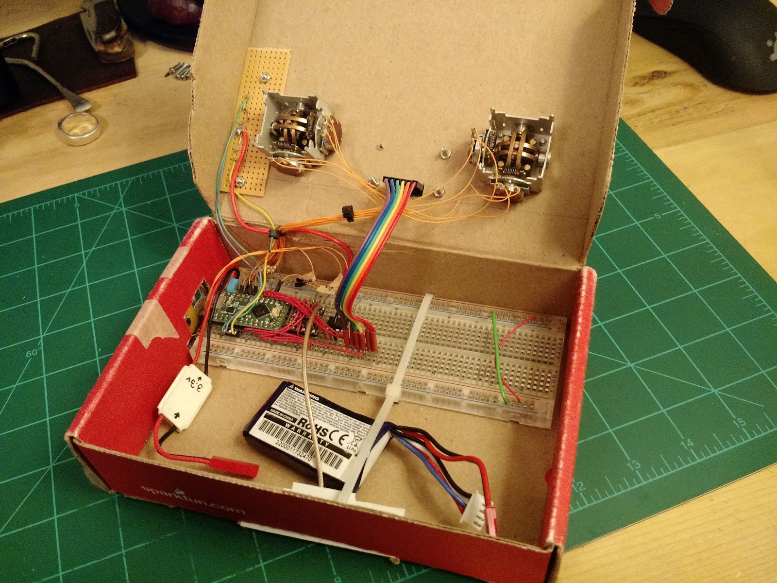
Between that difficulty and construction of the platform controller I've created a temporary controller using joysticks.


I later added an EEPROM chip and an LCD display which required a larger breadboard then would fit in the first cardboard housing. So...larger box.

So the Stewart platform idea didn't prove out. I've logged some flight time I still want something more intuitive then yaw/throttle on one stick, roll/pitch on another.
There was a short trend in RC using three-axis joysticks, which seems like the next best idea. (see http://www.singlestickstuff.com/the-history-of-the-single-stick/)
There was a short trend in RC using three-axis joysticks, which seems like the next best idea. (see http://www.singlestickstuff.com/the-history-of-the-single-stick/)
I've ordered parts and modeled out what I think the control panel will be.


At the time the Linx Technologies HumRC looked like a good option. But the module is a castellated SMD, so first I needed solder it to something(luckily Proto-Advantage makes a PLCC-32 to DIP-32 board in the layout that I need), and learn how to solder SMD along the way.


Next is to create the core functions for UART com with the HumRC devices.
I managed get two faulty 3.3v UBEC's from HobbyKing, subsequently replaced with some cheap buck converters from Deal Extreme.

Failed UBEC's are the top two, generic buck converters are the bottom two.
Thats was on March 29th, it's now June 11th, and this is what I've learned:)
Those HumRC chips are meant for keyfobs and not much more. The fastest I could get them to transmit and receive a 2 byte packet was 14ms. And that was after a month and a half of tuning the firmware and hardware.
After feeling satisfied that I could do no more to get them to meet my needs I spent a few nights researching alternatives, and ordered two that looked promising.
RFM69HCW
The chip is by HopeRF on a breakout from Sparkfun
HopeRF-RFM69HCW
Sparkfun - RFM69 Breakout (915Mhz)
Also has a couple public libraries like this one from LowPowerLabs.
Seemed easy enough, one complication they draw more current (130mA) then the Teensy LC or Arduino and handle so I connected one of my 11.1v Lipo batteries to a 3.3V buck converter and instantly fried both RF chips. Turns out if you connect the voltage source to the output side of the converter it just passes thru to the the input side, all 11.1volts. I reordered a pair and in the meantime moved on to the other set I had purchased.
ZETA-915
The chip is a Si4455 by Silicon Labs on a board by RF Solutions.
Silicon Labs has a Wireless Development Suite that generates source code for these.
Unfortunately it's meant for their own MCU's and compilers and has a variety of notions that don't directly port. A port for the Arduino is available here, however it was failing in the initialization process. After spending a few weeks debugging, pulling apart the library, config data, and reading the API doc, I eventually found that the config data was generated for a different chip revision, C. The ZETA uses Si4455 rev B. After generating a few configs for the correct revision it worked. I have at this point mostly re-written a library and just assume complete it, though the original port from dvdfreitag would probably work with a rev B config. Currently I have it configured for a 16 byte packet at 20kbs. In practice it can send/receive a packet per 10ms.

Transmitting from my workbench and driving with the receiver I was able to get ~600ft with a stable signal. Which is awesome, especially considering the line of sight went thru three clusters of trees and four houses.

The Frame
Working in Maya I made rough models of all the major components and played with a couple designs before settling on this pretty simple one. The arms will be 3d printed. The rest of the frame is just flat rectangles. Haven't decided on a material yet, may just go with wood.

The large "T" shaped thing in the perspective view is a 915 MHz dipole antenna which will get tucked and mounted on the side or back. Dimensions are noted in mm.
I then mocked it up in cardboard to sanity check the design.


Completed details like screw holes for the arms last night, ready to print.

Got the arms back from Shapeways, missing the end caps but otherwise very pleased with the results.


Initially I considered using some plastic sheeting for the body but I think it would have been too flimsy, could have been nice though since weighed all of 93 grams.

Instead I opted for a wood frame and proceeded with dry fit and assembly.


Will need to shorten some of those wires.
Bench Test
First wireless full power test ran as expected.
After many attempts to achieve lift off, all of which quickly resulted in upside down craft, broken props, and frustration, I determined to debug this I would need a blackbox. A EEPROM chip seemed ideal for this but soldering another set of wires and components onto my already rats nest of a prototype board seemed not worth the trouble so i went about designing a PCB(see below).
Designed and ordered three pcb versions of the flight control board.
Of course the day after I ordered them I caught a slight issue, fixed the design issue and ordered another set of 3.
Used Autodesk 123d Circuits to do the PCB design here.


Without components

Soldering completed.(except for yellow led, which I'm out of)


Tested firmware, seems good.
Need to include EEPROM lib and start write blackbox recording code.
Flight
Feb 3rd 2017 - Continued failure to stably lift off.
Feb 18th 2017 - It Lives!
Switched the 1806 motors I was using with some larger 2204's. I recorded the first test, which doesn't look like much, but I did follow it up with a few more take off's that were much higher, but not much more stable, lots of drifting and bouncing.
Have been taking it out to a park near me and have had several "successful" though short flights. Lots of drifting continues to be a problem. Will post videos soon.